Physically Installing the Clock

Before you mount the WB6000 Series Clock, you must find an appropriate physical location. To ensure that the clock functions properly, use these conditions:

  • Indoors, away from harsh environment conditions.
  • On a flat surface wall.
  • On a vibration-free surface.
  • In ambient temperature in the 32° to 110° F (0°C to 43°C) range.
  • In an area with less than 95% non-condensing humidity.
  • With an electrical outlet within four feet.
  • Not more than 328 wire feet (100 meters) away from the Ethernet hub/switch, if using the Ethernet connection.

To mount the WB6000 clock reader:
  1. Unlock the terminal with the supplied key.
  2. Slide the front of the terminal up slightly, then tilt the top towards you.
  3. Unplug any short jumper cables between the terminal and the base.
  4. Unhook the support links from their mating base pegs by gently pushing them inward, pressing the spring retaining clips toward the center.
  5. Separate the terminal and base.
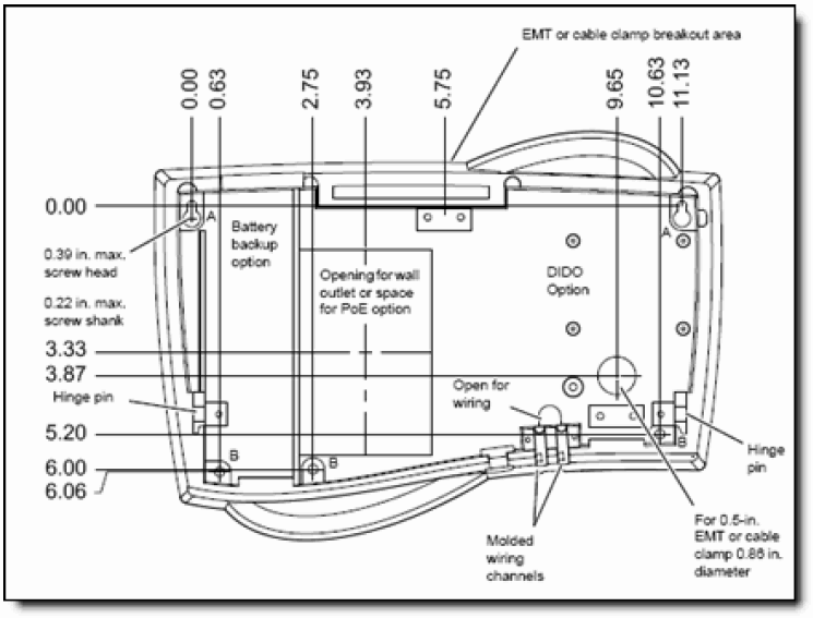
  6. Route the ethernet cable and power adapter wire, or just the power over ethernet (PoE) into the terminal through the available opening.

    See this diagram:

  7. Select an appropriate mounting surface.
  8. Mount the base on the wall using appropriate fasteners such as #10 pan-head screws (customer-supplied).
    1. Partially install the two upper screws in the wall, 50 inches above the floor.
    2. Place the keyhole slots in the base over these screws.
    3. Loosely install the remaining screws.
    4. Tighten all screws. Do not over-tighten.
  9. Ensure all required wiring is present and any cable clamps properly installed, following any applicable wiring codes.
  10. Reinstall the terminal on the base by re-engaging the terminal's support links on their mating base pegs, that you unhooked when separating the terminal, pressing the spring retaining clips toward the center. Be careful that wires do not get wedged when closing.
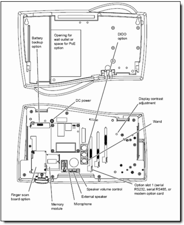
  11. Connect the power adapter cable to the DC power port if necessary, and the ethernet cable to the ethernet port, using this diagram: