| | Introduction to Entity Relationship ModelingEntity Relationship Modeling gives an insight to the
LN application
databases and the way in which they are interrelated. Entity Relationship Modeling is composed of two main building
blocks: - Entity types
- Entity relationships
These building blocks are interrelated and used in entity
relationship diagrams to show the relationships between the permanent storage
components. Together with the other components listed below, they let you
illustrate the diversity of relationships between the different databases. A
group of related diagrams make up an entity relationship model. Entity type A person, place, thing, or concept that you want to record
information about. An entity type is a group of entities with common attributes
and can be part of a diagram, such as Trucks. Entity A single occurrence of an entity type; a fact relevant to the
company, and about which information is permanently stored. For example: Truck-A and Truck-B.
Three kinds of entities exist: Logical entity Entities that have a meaning to the real world and are
comprised of one or more physical entities; they are defined on a higher
abstraction level. Physical entity Database tables of the
LN
application. Associative entity An entity used to link other entities. An associative entity
type is only used when there is a many-to-many relationship between two entity
types.
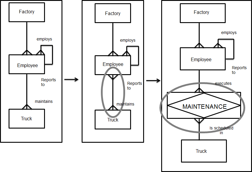
示例 There could be an M:N relationship between EMPLOYEE and TRUCK regarding maintenance. This relationship does not show which EMPLOYEE maintains which TRUCK. There are also other attributes to be considered, such as time
spent, part no. and so on. As a result of the ambiguity regarding the Many-to-many
relationship, the associative entity type MAINTENANCE can be defined. (See figure 2). Attribute A fact or non-decomposable piece of information describing an
entity type; for example, Number of wheels. Attribute value The value of an attribute; for example, 4 wheels. Relationship A reason of relevance for associating entities of one or two
entity types. Cardinality A specification of the number of possible entities for each
entity type of a pairing.
The three types of cardinality are as follows: One-to-One (1:1) A one-to-one relationship. Only one instance of entity type B
can be associated with only one instance of entity type A. One-to-Many (1:N) A one-to-many relationship. Multiple instances of entity type
B can be associated with only one instance of entity type A. Many-to-Many (M:N) A many-to-many relationship. Multiple instances of entity type
B can be associated with multiple instances of entity type A and
vice-versa.
Within Entity Relationship Modeling, there is no real difference
between logical and physical entities. The Entity Relationship Modeling procedure There are two different approaches for modeling
databases: - The first is the top down approach, which has to be used when
physical entity types, entity relationships and entity relationship diagrams
have not yet been created. Therefore, you have to manually create and define
all entity types and relationships.
- The second is reverse engineering, which is a quick way to
model entity relationship diagrams because you can select existing
database/table definitions for which a diagram will be created automatically.
Reverse engineering can only be used in the case of
LN.
Carrying out the Entity Relationship Modeling procedure results
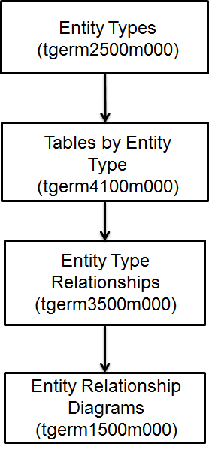
in a model that shows the relations between different databases. Figure 14.2 shows the steps in the Entity Relationship Modeling
top down procedure. 实体类型 (tgerm2500m000) To create the entity types, use the
实体类型 (tgerm2500m000). To define an entity type, complete the following
steps: - In the
实体类型 (tgerm2500m000) session, click New
- In the
实体类型 field, specify an id for the entity
type.
- Click
保存
| Key fields for the
实体类型详细资料 (tgerm2100s000) session | | Field | Description |
|---|
| 所属 ERP 子系统 | The package to which the entity type is related. | | 所属 Infor LN 模块 | The module to which the entity type is related. | | 链接至框图 | The entity-relationship diagram into which an entity type is
decomposed. At a different level in the DEM-Tool, you can see the entity-type
relationship between the current entity type and other entity types. | | 实体类型类别 | If you select this check box, the entity type is a physical
entity type or a logical entity type related to the Baan package. | | 相关实体类型 | If you select this check box, the entity type serves as a link
between two other entity types that have a many-to-many relationship between
them. |
按实体类型列出的表 (tgerm4100m000) To select one or more tables from the
Table Definitions (ttadv4526m000) session, and to link those tables to the selected
entity type, use the
按实体类型列出的表 (tgerm4100m000) session. To start this session: - On the 相应 menu of the
实体类型 (tgerm2500m000) session, click
链接 ERP 表至实体类型...
One entity type can be linked to several tables. The
interdependent relations between these tables are shown at different levels in
the Modeler. 实体类型关系 (tgerm3500m000) To list and define entity type relationships, use the
实体类型关系 (tgerm3500m000) session. The relationships listed in the
实体类型关系 (tgerm3500m000) session have been established between
the entity types listed in the
实体类型 (tgerm2500m000) session. To define entity type relationships, in the
实体类型关系详细资料 (tgerm3100s000) session, select the entity types
between which relationships are to be established. You can also define the
cardinality of the relationship between the selected entity types. In the case of an M:N relationship, an associative entity type
can be created, and a table can be selected from the
Table Definitions (ttadv4526m000) session to serve as a link between two entity
types. To define a relationship between two entity types, complete
the following steps: - In the
数据实体关系 field, specify an ID for the
relationship.
- In the
自实体类型 field, select the first entity type
involved in the relationship.
- In the
至实体类型 field, select the other entity type involved in the
relationship.
- In the
最小基本关系类型自 - 至 field, specify the number of possible entities
for each entity type of a pairing for the entity type you selected in the
自实体类型 field.
- In the
最小基本关系类型至 - 自 field, for the entity type you have selected in
the 至实体类型 field, specify the number of possible
entities per entity type of a pairing.
- Click
保存
| Key fields for the
实体类型关系详细资料 (tgerm3100s000) session | | Field | Description |
|---|
| 关系为子类型 | 如果选中此复选框,, the entity-type
relationship is between a subtype and a supertype entity type; it is used to
indicate that the supertype’s attribute also applies to the subtype. | | 存在物理数据库关系 | 如果选中此复选框,, the entity-type
relationship is between entity types that have tables from the
LN data dictionary
linked to them. | | 相关表 | An LN table used to link two entity types that have a many to many
relationship between them | | 无限 | 如果选中此复选框,, the maximum to-from
relationship is infinite. |
实体关系图 (tgerm1500m000) To create and maintain the entity-relationship diagrams, use the
实体关系图 (tgerm1500m000) session. An entity-relationship diagram is a
graphical design of the relational data model structure. The diagram shows a
multilevel structure that consists of entity types and entity-type
relationships. To create an entity-type relationship diagram, complete the
following steps: - In the
实体关系图 field, specify an ID for the
entity relationship diagram.
- In the
所有者 field, select the
LN user who created or
is responsible for the entity relationship diagram.
- Select who is authorized to modify the diagram by selecting one
of the check boxes under
修改者.
- Click
保存
| |